top of page

Engineering drawing and precision
This is an important part of the design process which applies to the prototype and manufacture stages. It involves the accuracy of 3D CAD modelling and 2D drawings to ensure obtaining quality results. Tolerancing is part of this process, as well as detailed materials specifications, finishes, engineering drawing symbols and assembly instructions.
Click on pictures where you want to see more detail on the drawing.
 For moulded plastic parts, it is often necessary to carry out detailed 2D drawings, with tolerances and other specifications, where precision is needed on most features | 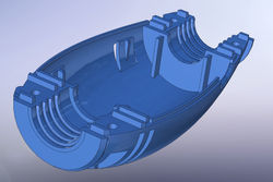 When manufacturers use 3D CAD models for moulded or cast parts, these are modelled with the accuracy needed for the tolerances that the manufacturing method has. The CAD models also include features need for the manufacturing process, such as draft angles. |
|---|---|
 Engineering drawings are also produced for other components that are not primarily mechanical, such as electronic PCBs. This is part of a process of work in collaboration with electronic engineering to achieve an optimum result for electronic and other technical parts. |  Engineering drawing for precision machined parts with production tolerances as small as +_ 0.05mm |
 Assembly drawings with Bill of Materials |  Engineering drawing for metal fabrications with welding, machining, tolerances and finishing specifications |
bottom of page